Analog Tach for HT?

Loquin is right about the shaping circuit, filter, and all that. He does know his stuff. I just want to add another $.25 of input.

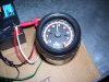
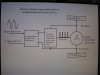
I built this same circuit in 1979 using individual parts for monitoring the engine speed of a Volkswagen diesel engine. There are no spark plugs. (It had a few other quirks, but that is for VW trivia seekers.) To sense rotation, I used a light bulb shining onto a photo resistor. The light beam pulsed onto the photo resistor when the engine camshaft gear rotated. (The cam gear had wide spokes, like a bicycle bottom bracket gear.) Then the rest of the circuit shaped the pulses and drove the needle of the analog tachometer (something from a local auto store). (The circuit came from a "cookbook".)

I calibrated the tach by pointing the photo resistor at a florescent light. Those lights pulse at 120 times per second, or the equivalent of 7200 rpm. After carefully removing the glass face of the tach, the readout paper was renumbered using Labelmaker tape.

It worked as long as the incandescent bulb did not burn out. If burned out, the needle swung all over the place until I replaced the bulb.

The spark plug wire is one way of picking up engine activity, there are other ways.

I looked high and low for analog tachs for bicycles. In the long run, they would probably cost more than the TinyTach or SenDec that I use. Solid state equipment is also almost always more durable than fragile moving needles.

But if anyone finds an analog tach for bicycles, please post details!
 
I know you can get the digital tachs for these engines but I cant find anything on a analog tach for a HT... has anyone tried this or know where a person could buy one?

Could you pull one from an old Honda or Kawasaki MC basket case?

Rick
 
Could you pull one from an old Honda or Kawasaki MC basket case?

Rick
Well, yes, you ... could. But, the issue with this approach is that they are typically cable driven, mechanical speedo's. So, you would need to get the engine rotation (before the clutch) transferred to a speedo cable, and at the right RPM. Gearing to get 6000 RPM engine speed down to apx. 1500 RPM, AND get a new dial face behind the needle on the speedo.
 
Last edited:
Hi Everyone -

I think an analog tachometer for a Chinese engine can be done using off-the-shelf parts. I will spare everyone the long, gory details, but the bottom line is you have to use that one controversial component of every Chinese two-stroke...

The White Wire.

That's right, the White Wire. Disregard trying to use the spark plug wire if you want to use an analog tach. You need an analog signal, specifically the sine wave voltage that appears on the white wire. The sine wave frequency and voltage varies with engine RPM. Those are the keys to using an analog tach.

Get the tach of choice at the local auto supply store. The tachometer must say to connect it to the distributor or coil of the car; most tachs do. I purchased one that would look good on a bicycle for about $32 from an auto parts chain store and I was out the door. It even has a light to illuminate the face of the meter for night riding.

The provided diagrams should be fairly self-explanatory. The sine wave voltage coming out of the magneto gets rectified into TWO positive-going pulses. The tach has a selector switch for 8, 6, and 4-cylinder engines. Set the switch to only "4". This allows the tach to sense the pulses fed into it and display RPM directly onto the meter face. There is no other alteration to the purchased tachometer.

The battery is a 3.3 Amp-hour battery from a local hardware store. A charger had to be purchased as well. If you have a 5000 cranking amp 12 volt truck battery, you can use it. The tach draws only 35 milliamps; it won't hurt either battery if wired correctly.

My test frequency of commercial electricity is available at 60 Hz (common knowledge). That is also the same frequency as a Chinese engine magneto output at exactly 3600 rpm. By using this, I proved that the circuit you see worked at this one frequency, simulating an engine spinning at 3600 rpm. The voltage being fed to the rectifier was 10 volts AC, right in the middle of the magnitude range produced by the magneto at operating rpm.

There is still testing to be done, to include with a real engine. Just because it works on a test bench does not guarantee success in the field. But it is a good indication of success.

If you are interested in pursuing this, please do so. Share your findings with the rest of us; I probably will need a few weeks or so of more time for testing.

MikeJ
 

Attachments

  • 100_1622.JPG
    100_1622.JPG
    205.7 KB · Views: 358
  • 100_1624.JPG
    100_1624.JPG
    219 KB · Views: 330
  • 100_1634.JPG
    100_1634.JPG
    177.7 KB · Views: 748
  • 100_1635.JPG
    100_1635.JPG
    183.5 KB · Views: 387
  • 100_1637.JPG
    100_1637.JPG
    189.5 KB · Views: 341
Last edited:
Umm. For a digital analog tach, wouldn't you just hook it up to the sparkplug wire?


Though, when I think "analog", what I'm really thinking is "not digital".

For a cabled tach, I would go off the flower nut (which is threaded in the center) and gear it to match or off the smaller bevel wheel, and just drill a small hole in the center of the bolt to mount to, which is really the true RPM of the motor.

Or is this not right?


:::EDIT ADD:::

Found em : "Inductive Tachometers" or "Inductive Hour Meter" is what they're called, they do exist, and there's no work to be done, as it just counts a spark as a rotation.
 
Last edited:
Mike;

Wanted to being up a couple of points:

first, if you us a bridge rectifier with the white wire output from the HT, you must use an isolated ground on any circuitry after the bridge - else, half of the bridge gets shorted. So, your battery/tach circuit must use a separate, isolated ground.

Second; I believe that you'll want to add a 12.6V zener diode across the 3.3K resistor. Since the mag voltage increases with RPM, it's possible that the voltage could damage the tach at high RPMs. The zener would eliminate this possibility. I 'marked up' your first schematic to show this diode...
 

Attachments

  • 100_1634a.JPG
    100_1634a.JPG
    74.5 KB · Views: 325
Last edited:
Hi Loquin -

Thanks for responding. Yes, you are correct that the engine and tach circuit must be of separate grounds. I tried what you noted here, tying grounds of the source and tach together. RPM dropped to exactly half immediately, indicating rectifying diodes got bypassed. No harm was done, I just noted "Do not do that again!"

The Zener diode addition is a good idea; I did not think of limiting voltage input to the tach product. Someone posted in another thread that they observed +18 volts after rectifying and filtering the white wire output at high rpm. I would think that tach manufacturers put in overvoltage protection, but I have yet to see proof. An extra Zener would be trivial to install.

IF manufacturers use the 555 timer chip to make a one-shot circuit to drive the D'arsonval movement with PWM, the trigger fires at around 1/3 battery voltage. Trigger voltage probably should not exceed battery voltage, so I would recommend going for a 9 volt Zener. That still gives lots of room to trigger an output pulse. I have to play with that and observe if the engine performance is affected.

But first, put priorities in line: 1) Replace engine (wimpy at this >5500 ft high altitude; is good at below 3000 feet altitude) with something much bigger, 2) shake out bugs, 3) put on a few hundred miles. Interleave the analog tach effort when not riding.

Will catch you later!
MikeJ
 
Back
Top