Cheap reed valve setup

V8bacon

New Member
Local time
2:53 AM
Joined
Oct 3, 2016
Messages
3
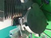
Hello I'm new to the forum and have been working on these engines for a couple years now . I have been working on a reed vavle setup for a ported engine with crankcase packing . I'm just playing around with some metal right now to see were this goes . Has anyone built a homemade reed vavle setup before ?
 

Attachments

  • image.jpg
    image.jpg
    177 KB · Views: 345
both I and lazylightning have.
mine was small and fit inside the intake port. it was homemade.
his was made for a moped and he fabricated the adaption to his engine. It turned out really good and he gets good power from it, his 21mm Dellorto carb, and torque pipe. He also increased the size of his transfer ports and it has a Jaguar CDI.
 
SDC10221.JPG
SDC10222.JPG
SDC10223.JPG
SDC10230.JPG
SDC10235.JPG
SDC10237.JPG
SDC10533.JPG
SDC10534.JPG
SDC10921.JPG
SDC10922.JPG
Hi!

Here's the setup I made. I used some pieces of 3mm thick cheap steel I cut from some square tubing profile used in construction. I used the semi-automatic wire feed welding machine, it makes welding as easy as pie. The one thing that needs to be taken into consideration in advance is the deformation of the construction due to welding. The mating surface with the valve insert and the mating surface of the intake tube hatch. This means the best thing to do is to make box walls to line up well within the bolt hole pattern so that you can use full removable bolts instead of welding studs into the construction. Bolts could hold the mating plate flt and tightly to a thick steel plate so that it doesn't deform while welding. Then the little areas close to the bolt heads could be welded with the bolts removed for minimum risk. Also, you could just try to weld it with the bolts in and just let them get welded in a bit. But no reason to weld all the way around the bolt head and risk more deformation. The steel deforms significantly as it cools. I had this problem and I had to repair the flatness of the mating surface by using jbweld. No picnic at all. Here's some pics from different stages.
 
SDC10535.JPG
SDC10918.JPG
SDC10919.JPG
SDC10920.JPG
SDC10529.JPG
SDC10532.JPG
SDC10877.JPG
SDC10878.JPG
SDC10887.JPG
SDC10888.JPG
I cut the divider out of the middle of the valve and used single large pieces of carbon sheet for the reeds. I left part of the dividers in since it was not going to increase flow by removing all of them and the remainder helps stabilize the reeds. The distance from the reed valve nose to the little hex-key-tool-bolt-heads inside of the reed is also important. Dont use normal bolts, it will be a hassle to tighten them and you probably wont be able to tighten it enough. If the reed doesn't fit inside, then you cant bolt it down. Mine was close, so I used a second gasket to space it away a bit. I used locktite when bolting the reed box to the cylinder because you cant tighten them from the outside, and when its all together you dont want them coming loose. There was alot of free space inside the reed box around the reed valve due to design flaw, so I cut and shaped chunks of industrial teflon that is easily bought here. The carbon sheet material from Malossi has a slight curve to it. It is concave to the printed side. So you want to use the printed side in towards the valve when placing the reeds to the valve. I don't know about other brands of carbon reed sheet.
 
SDC10254.JPG The greatest part of the job was modifying the cylinder. I use a shorter conrod from a Yamaha Jog, so I have to remove 5mm from the bottom of the cylinder using a special rig in a lathe. Before doing that I welded some aluminum material to the outside area of the transfer channel onto the last fin so that when I lathed it down there would be a nice flat mating surface that is wider than stock. This is because I widened the transfer channels to such a degree, that the walls of the transfer channels to the fins was about two millimeters thick. Note! The stock mating surface area is wider than the rest of the transfer walls(to the fin side) and you should be careful not to widen it so much as to go through the wall to the fins and get yourself a hole that will be difficult to repair with jbweld and always be in the back of your mind as a potential air leak.
SDC10248.JPG
SDC10249.JPG
SDC10250.JPG
SDC10251.JPG
SDC10252.JPG
SDC10253.JPG
SDC10254.JPG
SDC10255.JPG
SDC10256.JPG
SDC10257.JPG
 
Last edited:
Here you can see how I made the booster port. It was wrong and I corrected it. I took out the dividing material in the middle and added jbweld to the sides because it shouldn't be as wide as the intake. In the las photo, you can see how I welded aluminum material to the transfer channel areas on the carters to make a wider mating surface for different builds in the future.

SDC10273.JPG
SDC10275.JPG
SDC10276.JPG
SDC10277.JPG
SDC10278.JPG
SDC10279.JPG
SDC10280.JPG
SDC10281.JPG
SDC10282.JPG
TvKd-DyY0fI.jpg
 
Back
Top