T
Tinker1980
Guest
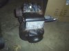
Boredom and spare engines are the blame for this. I found, around springtime, three vertical shaft engines - one is a tecumseh (with an electric starter!!) and refuses to run right, the other two are B&S engines, both did run after some carb cleaning, but one was missing parts from it's recoil starter, so it became spare parts. This left me with an older style Briggs engine with the ball-bearing style recoil starter. I removed the crankcase cover (The entire bottom of the crankcase) from my vertical engine, and the crankcase cover from a horizontal B&S engine I had. Also removed shrouds, to see the flywheels better. I learned some things:
1.) The only difference, internally, is the dipper on the con-rod of the horizontal engine. The vertical engine uses a gear driven spinning device. One can put the dipper on the con-rod of the vertical engine, and it will work.
2.) At least with the engines I had in front of me, the flywheels were the same weight. I removed both of them, and they weighed the same amount, so I know the vertical engine will idle without a blade on it.
Why use a vertical shaft engine at all, if I have a horizontal one to compare it to? Mounting. I wanted to try a friction drive rack mount setup. A horizontal engine has it's mounts on the bottom, , so you'd have to build some kind of L-Shaped setup off the side of your rack mount. (Or use a HF 2.5 engine, which has mounts on the bottom AND the side)
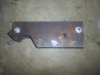
The lawnmower engine has a three bolt pattern on it, and I intend to make a t-shaped part that will reach all three bolts, but miss the crank itself.
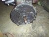
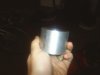
I can't use commonly available rollers for my design, since a 1.5" roller at 3600 rpm gives me a speed of around 16 MPH. I got lucky in that respect, my brother brought me a piece of scrap from where he works. It's the very end of a piece of 7000 aluminum round bar that is 2.75" diameter, about 2.5" thick. I wanted a roller that was 2.25"-2.5" diameter, but for free I won't complain. It goes to the machine shop for a .875 hole soon.
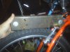
Thoughts on this setup? I have pictures but nothing has been assembled yet. The part you see on the bicycle will have angle mounted to it for the motor mounts.
-Mark
1.) The only difference, internally, is the dipper on the con-rod of the horizontal engine. The vertical engine uses a gear driven spinning device. One can put the dipper on the con-rod of the vertical engine, and it will work.
2.) At least with the engines I had in front of me, the flywheels were the same weight. I removed both of them, and they weighed the same amount, so I know the vertical engine will idle without a blade on it.
Why use a vertical shaft engine at all, if I have a horizontal one to compare it to? Mounting. I wanted to try a friction drive rack mount setup. A horizontal engine has it's mounts on the bottom, , so you'd have to build some kind of L-Shaped setup off the side of your rack mount. (Or use a HF 2.5 engine, which has mounts on the bottom AND the side)
The lawnmower engine has a three bolt pattern on it, and I intend to make a t-shaped part that will reach all three bolts, but miss the crank itself.
I can't use commonly available rollers for my design, since a 1.5" roller at 3600 rpm gives me a speed of around 16 MPH. I got lucky in that respect, my brother brought me a piece of scrap from where he works. It's the very end of a piece of 7000 aluminum round bar that is 2.75" diameter, about 2.5" thick. I wanted a roller that was 2.25"-2.5" diameter, but for free I won't complain. It goes to the machine shop for a .875 hole soon.
Thoughts on this setup? I have pictures but nothing has been assembled yet. The part you see on the bicycle will have angle mounted to it for the motor mounts.
-Mark