safe said:
Hopefully that helps makes sense of things.
Yeah, I spent a bit of time the other day following the cells up down and sideways but it all makes sense now.
I did promise some preliminary results... here's a scenario with 6 16AWG wires per phase (in 2 sets of 3) and an ~0.8mm air gap. At 12A per phase, 60% duty cycle bipolar, FEMM gives me an average of 2.73 N for 2 poles (manually accumulated over 10 points)
which works out to 49.14N at an effective radius of 78.75mm, that's 3.87Nm.
This is in roughly the right range - anything over around 5N and I'll be in serious doubt of my rotor and stator integrity
Copper losses are around 25W at this current level. Makes me wish I could get square magnet wire in 16AGW...
Long story short, with a 700C/25 tyre, this is giving a delivered power of 192W at 60 kph, efficiency around 88.5% ... still some optimization to go, there...
safe said:
I suspect that your 88% for maximum efficiency is about right. Everyone expects anything built with a Halbach Array to automatically jump in efficiency to 96% like the CSIRO, but that doesn't happen for free... you have to do your math.
Indeed you do - but perhaps you miss my intention... this motor is being designed as a high-speed cruising power-assist for a fully faired velomobile on the open road: 192W at 60kph should be far in excess of the
total power required at that speed, if I get my aerodynamics right; this is the
start of my envelope, not the end of it. At 60kph, typical motor loading would be 50-75W, and 'Long range cruising speed' will be ~ 90kph, with the motor operating at 100-125W (with the rider supplying another ~100W). At 90kph and 125W delivered power in this configuration, copper losses are only ~5W, for an efficiency of... 96% or so

... at 90kph / 200W, copper losses rise to around 13W for an efficiency of around 94%, and at 250W, maximum theoretical efficiency is still in excess of 92%... All that said, I haven't worked out how to model end effects on the inner and outer edges of the rotor yet, I'm just hoping simulation with N40 and no end-effect modelling will hold for real N42 and real end-effects...
Next phase will be getting things running from octave to automate testing of stator parameters (conductor count and size, particularly) - I've looked at an example script, it doesn't seem too hard. I'd really like to do it with one layer of copper, as construction would be greatly simplified, but I'll just have to see how it goes.
An interesting effect I noticed is that force does not vary linearly with current in the simulation... turns out I had a small offset in my force calculations with 0 current in all circuits. Looks like reducing mesh size in the airgap tightens it up nicely.
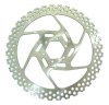
In other news, a pic of the rotors which will be used in construction of the... rotor:
Promax 180mm (DT-180C) - the brake surface has I.D ~145mm, OD ~180mm at the pointy bits, so it should be just about right... the drilling happens to have 36 holes in each ring, too - which is serendipitous for lining up a large number magnets at 5 degree increments: the poles and halbach magnets will line up with the peaks and troughs of the outer edge...
Lastly, I've realised another factor which may make tight tolerances more bearable - if the coil timing is slightly advanced under heavy load, the windings will pull towards the centre of the gap - the side closest to the rotor will be pushed away more strongly, producing a magnetic bearing effect which hopefully might keep things apart if they start flexing at high torque. Conversely, if the timing is slightly retarded, the coils will pull the stator towards the sides of the rotor. The opposite is true under braking. Methinks I shall definitely be building my own controller, with sensors - this is not the kind of thing I trust to an off-the-shelf controller to be designed for (a sensored controller with an adjustible hall effect sensor might do the trick, but I'd rather not risk it).