Live Axle wheel

I would like to have some adjustment in the position of the wheel, the above suggestion seems a bit permanent.
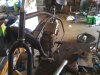
Random, as pictured in that instructional guide, the hubs are permanently werlded to the axle, yes.

They needn't be. Simply make the flanges and weld them on an appropriate sized piece of good steel tubing to fit over your axle. If you use heavy wall tubing, you could matching key the axle and the inside of the hub center tube, which would allow limited side to side adjustment. Alternatively, you could key slot the axle and leave appropriate tabs on the central hole you create in the hub flange.

Be creative, in other words, Myself, I'd make 3 identical shallow key slots in the axle 120 degrees apart, and create three locking tabs to fit in each hub flange disc. Do that, and the wheel is positively locked to co-rotate with the axle while leaving you side to side adjustment.

As pictured below.
 

Attachments

  • Hub design.jpg
    Hub design.jpg
    26.7 KB · Views: 252
Last edited:
Thanks for the help SSimon, I'll have to brainstorm about it. The motor is mounted already, it was a pain to get it to fit, but we managed it, we had to cut the seat post out and somehow got it to fit. Ill post pictures when its finished.
 
Randomco,

I would be very interested to see how the motor is mounnted, along with lots and lots of other users here!

Please be sure to post pictures when you can, there have been more then a few who have thought of this setup and not been able to do it.

Regards,

Steve
 
I must mention that mounting this motor rendered pedaling useless, so I will have to mount the pedals possibly further forward, or make a wider crank.
 
I must mention that mounting this motor rendered pedaling useless, so I will have to mount the pedals possibly further forward, or make a wider crank.

Can you tease us with a quick picture of the build so far?

I am very interested in how that engine is mounted...

Steve
 
I will snap a few pictures when I get off work later today, it is still very early in the build, and the motor mounts are just tacked in now, but you can get the idea.
 
Here a few photos of the progress, the engine mount is not complete by any means, just one tack weld to hold it in place, but you get the idea.
 

Attachments

  • bike 002.jpg
    bike 002.jpg
    107.8 KB · Views: 251
  • bike 003.jpg
    bike 003.jpg
    101.7 KB · Views: 238
  • bike 004.jpg
    bike 004.jpg
    105.7 KB · Views: 251
  • bike 001.jpg
    bike 001.jpg
    108 KB · Views: 239
Very nice work so far on fitting the engine in and the initial mock up you have...

Any ideas on what you are going to do yet for a back wheel and a live axle?
 
I plan on cutting off the stock (for lack of the correct terminology) slotted rear wheel axle mount, and then weld a plate to mount the bearing flanges. I will have an axle that is approx. 8" across. The wheel will be in the middle of the rear "forks" as normal. If looking at the rear of the bike, I will have a 10" v-belt pulley on the left, outside of the rear forks, on the live axle. On the right of the rear forks will be an 8" go kart disc brake with the caliper mounted to the forks. I will most likely weld a steel plate to the rear forks with slotted holes that match the bearing flange bolt pattern, in order to slide the entire rear axle assembly back to tighten the belt from the rear pulley to the centrifugal clutch on the motor.
 
Back
Top