The AC Induction Motor Ebike Project

Adding A Charge Pump?

I'm "firm" on the idea that a "toy" ebike should not require more than 48 volts for a battery. To expect a kid to be trusted with a 120 volt DC battery is to invite disaster.

But it might not be necessary to configure the battery as 120 VDC.

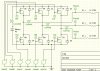
PWM controllers usually have a sort of "preload" stage where a row of capacitors temporarily store the battery energy before passing to the MOSFET's. Why not just add a second "preload" stage with a charge pump and step up the voltage to double?

So 48 VDC becomes 96 VDC...

More specifically the battery chemistry values would start at:

SLA - 13 * 4 = 52 volts * 2 = 104 VDC

NiCad - 1.3 * 40 = 52 volts * 2 = 104 VDC

At 104 VDC you are pretty close to the standard voltage that these little AC Induction motors are designed for, so the rewinding is not necessary or as important. It might be possible to find the exact motor you need "off the shelf" and not even need to fiddle with it.

So this inverter would need:

Three Phase AC power.

Variable Frequency Drive (VFD).

"Step Up" inverter that would double the voltage. (or more)

Be designed to be as efficient as possible. (90% or better)

Must have a strict 1000 watt input restriction.

TUAPFAIE2_aug2007.gif


What's radically different with the AC Induction motor verses the DC permanent magnet motors (brushed or brushless) is that voltage and motor rpm are UNRELATED. This is really cool because it means that the more voltage you use just increases the efficiency of the motor with no change in the motor speed. (efficiency improves up to a point... I was reading how you can actually go too high with voltage too)

The central mechanical problem that ebikes have dealt with is that all the permanent magnet motors require the motor rpm to be very HIGH before they gain their best efficiency. These motors also become limited in the width of their usable powerband, so you are forced to use gears if you want to cover all possible situations.

With the AC Induction motor the efficiency is best when a certain amount of "slip" is taking place. VFD's allow you to target the ideal "slip" and with the use of PWM it's possible to adjust the voltage at lower frequency to eliminate the excess current problem.

Will the AC Induction motor be the future of ebikes?

We will see...
 
Last edited:
Product Near What Is Desired

http://www.donrowe.com/inverters/wagan_1000.html

wagan_1000.jpg


Maximum efficiency approximately 90%
No-load draw < .95 ADC
Output Wave Form Modified Sinewave
Input voltage range 12V (10-15 VDC)
Output voltage range 115 VAC 60 HZ
Low voltage alarm 10.5 +/- 0.5 VDC
Low voltage shutdown 9.5 +/- 0.5 VDC
Thermal shutdown yes
AC receptacles 3
Warranty 1 year
Inverter weight (incl. cables) 4.2 lbs
Shipping weight 5 lbs
Product dimensions 10.75"x 5.5"x 2.75"


Special $79

-----------------------------

It's not a variable frequency drive (VFD) and the output isn't Three Phase power (so in some ways this is nothing like what is needed) but the efficiency as an example looks about right. 90% efficiency would compare to the 95% efficiency that a simple PWM controller normally attains.

Also, I would want to start at 48 VDC and not 12 VDC.

So it's sorta kind close...
 
Last edited:
Magnet Wire Thermal Rating

The stock motor was rated as being able to handle 40C maximum. This means that the wires were so poorly insulated that temperatures not much more than a really hot day could melt something. :sick:

Magnet Wire comes with insulation that is rated at 200C.

That's a huge difference and should mean that you would be able to drive these motors much harder than one would think based on the horsepower rating.

It would appear that rewinding is a necessity.
 
The Torque Equation

Having gotten very familiar with the equations for permanent magnet motors it is fascinating to study the differences that come about in the AC Induction motor. (Three Phase)

While this formula might look rather nasty, with a short explanation it's not that bad. Basically the Torque of an AC Induction motor can be viewed from one of two perspectives. You can look at it from the perspective of current or you can look at it from the perspective of voltage. (see the gray boxes)

attachment.php


...what's interesting is that both the current side and the voltage side vary IN THE SAME WAY such that they both increase as a SQUARED factor.

The thing to realize is that with the simple V = IR we can say how things should behave based on the motors resistance. But since I^2 * R losses are what define the efficiency it's not hard to see that there's no downside to increasing voltage at the expense of current. Those strange "X" variables are "Reactance" which is something having to do with the way the rotor is behaving. (sort of analogous to backEMF for permanent magnet motors)

The AC Induction motor is UNLIKE the permanent magnet motor in that when you increase the voltage all you are doing is increasing efficiency... the motor speed is unchanged. If you double the voltage of a permanent magnet motor you double the motor speed. Double the voltage on an AC Induction motor and the speed is unchanged.

So for this project one has to ask the question:

"Do I lose more in efficiency by stepping up the voltage or by running the motor at a lower voltage?"

...and that's harder to figure out. My guess is that it "depends" on things like what frequency you are driving the motor. Clearly at the lower frequencies when voltage demands are low THERE IS NO NEED for increasing the voltage! But then once you cross a certain point your torque will fade away if you can't supply more voltage. (the "Breakdown Torque" seems to be sensitive to voltage and occurs earlier with less voltage)

So in the end... it's "interesting"... hmmmmmm....

Ideally one gets the maximum torque legally allowed (based on the 1000 watt input, 750 watt average output rule) from the lowest rpms all the way to the point when the voltage becomes insufficient. The lower voltage option makes for a great low end with high efficiency because of the LACK of a step up phase, but it loses steam above a certain frequency. The stepped up voltage is better at higher frequencies and delivers more "punch" on the top end, but having to step up the voltage means an automatic 5%-10% loss.

The most simple form of control is called V/F which is "Voltage/Frequency" and the idea is that you match the effective voltage to the frequency while adding a small correction factor.

b7097_f8.gif


...you can see how on the lower frequencies you don't need really high voltage, but at higher frequencies you do. Higher voltage means you have a wider powerband and unlike the permanent magnet motor the efficiency is based on the load and not the rpm. You can expect higher "effective" efficiency if you are constantly using full load.

This makes me think back to the issue of the either 20 mph or 30 mph (depends on local laws) speed limit on these ebikes. For the machine that is targeted as "street legal" there is little need to run higher voltage because you can be satisfied with half. (48 volts) So it might be possible to sell the bike "as is" and it would basically have a self limiting effect above a certain speed based on voltage. (power drops off) The "racer" mode would involve increasing the voltage which would "fill out" those higher frequencies.

This looks very good for a product. :cool:

The difference between the street legal version and the race version would be the presence of a step up voltage converter or a reconfigured battery. The stock bike would run at 48 volts and the race machine much higher.

The proof of all this will be to try building a simple controller that uses V/F control with simple ramping and 48 volts. Try that out. Then build/buy a step up converter to increase the voltage and try that out. Building the step up portion is not a requirement initially. (it really only makes sense at the higher frequencies... higher speeds) And for a race machine it makes sense to allow more than 48 volts.

----------------------------

On my newer bike I have 12 sets of 24 volts in the battery. I was planning on assembling them as two sets of six each which delivers:

24 volts * 2 (sets of 6) = 48 volts (130 amps peak)

...but if I really wanted to go crazy on this high voltage stuff (and probably get myself killed) then I could connect the battery as:

24 volts * 12 (sets of 1) = 288 volts (20 amps peak)

...so I could test the upper limits pretty easily without needing the step up converter. :eek:

(however, a MOSFET based design couldn't handle that kind of voltage, would need IGBT's)
 

Attachments

  • Torque Equation.jpg
    Torque Equation.jpg
    38.2 KB · Views: 1,870
Last edited:
How Should The Throttle Work?

Unlike the DC permanent magnet motors which operate on voltage as their control mechanism the AC Induction motor has a rather complex behavior based on voltage, current and frequency.

If you "didn't" have a throttle and instead just had a simple toggle switch then you would get a standing start powerband shape like this:

02473.png


...what's interesting is that the maximum torque occurs as the rotor speed approaches the synchronous speed. (80% synchronous speed means 20% "slip") There is a "sweet spot" in AC Induction motors that you want to be able to hit all the way from zero rpm up to the maximum rpm. (and it's a moving target)

It's not a simple problem....

The most simple technique is to just match voltage to frequency (V/F) and that does a fairly good job if you ramp things up and down very slowly. Realistically it's not a great control scheme as the chances are that you will find on the road conditions that throw things off so that frequency is not well matched with motor speed.

Some kind of feedback or modeling is needed...

The most "hardcore" technique is something called DTC "Direct Torque Control" where they build a sort of model in the software of the controller that is then used to control the motor. You sort of "tune" the controller to the motor in a pre-starting training phase. While this is a cool idea it's pretty complicated and not entirely what I want.

The rules that matter to EBRR ("Electric Bicycle Road Racing") rules as I envision them is that there is a need to restrict power to a maximum of 1000 watts on the input side. Since efficiency varies in some parts of the powerband you might get 60% efficiency at lower rpm while at others you will get the maximum of about 80% effficiency. Compared to DC permanent magnet motors there should be a slight increase in efficiency at the lower rpms.

"Slip"

Current is increased when the "slip" of the motor is increased or when the voltage is reduced. "Slip" is the difference between the rotor speed verses the frequency of the stator which is trying to accelerate the rotor.

At first I thought that I would want to use the throttle to control FREQUENCY... but now I'm thinking that I want to control INPUT POWER.

...that's a subtle difference. If I have a current sensor on the main battery wires then I can measure the actual total power coming from the battery itself. The controller could have a "pulldown" functionality where the frequency is allowed to rise just enough to allow for the power as allowed by the throttle.

Examples:

Rotor Speed 0% - Throttle 100% - The controller will try to raise the frequency which increases the "slip" and causes current to flow. Once the current matches the 1000 watt input limit the frequency is prevented from rising any further.

Rotor Speed 50% - Throttle 50% - The controller will either try to raise the frequency or lower the frequency as needed to produce the level of "slip" that will correspond to a 500 watt input level.

...and so on.

Anyway, that's my thinking at the moment. Voltage, current and frequency are controlled is such a way that total input power is the central issue.

Repeating the core issues of the whole project... the whole reason for using AC Induction motors for ebikes would be to get the maximum efficiency possible given a fixed 1000 watt input while applying it across the widest powerband. (and being able to eliminate geardown units) Power input levels above 1000 watts are ignored because they are not legal power levels.
 
Last edited:
The Current Sensor Question...

It's always a good idea to actually run a SPICE simulation of whatever you are thinking about just to make sure that things behave the way you think they behave.

My goal was to figure out if a single current sensor placed near the battery would be adequate to let me know how much current overall is going through the Three Phase Bridge circuit.

The answer appears to be "Yes"... which is what I expected.

Just a good idea to double and triple check your own logic to be sure you aren't making a mistake.

The parameters are way off from what would be really used, but I can focus on tweeking them with time.

----------------------------

What this means is my basic premise is intact... that a 1000 watt input could easily be metered by a simple current sensor. Something like a WattsUp meter could be installed and then the fine tuning of the current limiting could be done by observing the maximum power (watts) that is being delivered and doing a simple throttle "pulldown". The same ideas I've used with previous Armature Current Limiting circuits will apply.
 

Attachments

  • Three Phase Bridge Circuit 001.jpg
    Three Phase Bridge Circuit 001.jpg
    225.9 KB · Views: 781
  • CurrentABC.jpg
    CurrentABC.jpg
    91.3 KB · Views: 672
  • CurrentAll.jpg
    CurrentAll.jpg
    65.6 KB · Views: 652
Last edited:
The Consequences of Constant Power Control

Constant Power control has it's consequences. With the Induction motor the maximum efficiency occurs with a specific amount of "slip". This "slip" is the difference between the rotor speed and the speed that the stator frequency is trying to realize. When the gap between the two is large (large "slip") the motors reaction is to try to compensate with more current. Beyond about 5% - 10% "slip" the efficiency begins to drop and the motor wires will increase their heating.

In a Constant Power control scheme the "slip" will be highest at low frequencies and rpms when the load is high. As the load is removed (as the bike accelerates) the control will react by increasing the frequency.

So the expectation would be:

Low rpm, full throttle... high "slip"... slightly lowered efficiency... good power...

Middle rpm, full throttle... ideal "slip"... ideal efficiency... great power...

High rpm, full throttle... very low "slip"... lowered efficiency... slowly fading power...

---------------------------

How this differs from the permenant magnet motor is that with a permanent magnet the best power occurs earlier than the best efficiency. (typically) This means that when it comes to gearing you are forced to gear a little lower than you would like and since there is a fixed rpm limit (no load speed) you find yourself pretty much capped on top speed. This forces you to explore multispeed gearing or add more brute force power to compensate.

The AC Induction motor can also be overvolted. Overvolting means that you apply more volts at higher frequecies and that will fill out those higher rpms that would otherwise be sagging at normal voltage. AC Induction motors sort of get something for "free" with more voltage... up to a point of course. At some point the rotor will start to saturate if you drive it too hard. (all things have limits)

---------------------------

Sort of a simple thing to remember:

Permanent magnet motors operate best at lower loads and higher rpm.

AC Induction motors operate better under higher loads and are more flexible in their control options. (there are many)
 
Last edited:
The Ebay Solution

What if you could just buy a VFD and an Inverter?

:D You could start with a 24 VDC to 240 VAC Inverter that could cost about $50 and have an electrical efficiency of 90% or more.

:D Then you get a 240 VAC VFD (variable frequency drive) that is already completely optimized for everything you could imagine. (they have all kinds of surplus stuff on ebay for low $$$)

...put them together and you have a 240 VAC ebike. :D

But the battery connection is only 24 volts so it's safer to operate.

------------------------

(it's not the "ideal" because you have an unnecessary middle step, but if the price is low enough it might be worth doing as a sort of test case just to get the AC Induction motor running quickly)
 
Last edited:
How To Build A Good 1000 Watt AC Induction Motor

I've included a pdf file that talks about the central issues involving small AC Induction motors. I can summarize what they write by saying when it comes to efficiency:

Stator I2R Losses: More Poles Reduces Losses.

Rotor I2R Losses: More Poles Reduces Losses.

Core (Iron) Losses: No Change

Friction and Windage and Stray Load Losses: No Change

---------------------------------

One thing to note here however is that increasing the number of poles (reducing the motor rpm) also has the effect of LOWERING the torque that the motor produces.

Meanwhile (outside of the pdf) when we consider voltage we see that if we double the voltage the effect will be to cut the current in half and that means (because of I2R heating) that we actually reduce the heat by a factor of four.

So what does this mean?

It "seems" like the ideal way to wire a small motor is to use smaller wire than is "stock" and INCREASE the number of turns in order compensate for a 4 pole design. (assuming you are starting with a 2 pole like I am) Now you have a motor with much higher resistance and inductance than had you used the same wire gauge, but because you are now using twice the voltage it becomes easy to get the flux you need.

More turns, thinner wire, 4 pole, higher voltage.

Where things get tricky is in the control area. When at really low frequency the normal way to run a V/F (voltage/frequency) control scheme is to make sure that the voltage and frequency mostly match with a small boost compensation at low frequency. If you allow the voltage to rise too high while the frequency is too low you will get a rapid increase in current which could burn out the thinner wires I have in mind. So from the "Constant Power" control scheme which looks at total power input you might need to add some kind of a current limit on the individual phase wires themselves. "Overall Power" can be metered by a current sensor on the battery, but deep in the guts of the motor you have the phase current which is actually the one that will burn up the motor. So it might be necessary to have multiple current limiting sensors.

Howewer, since most V/F control schemes have a "boost factor" at lower frequency to compensate for losses maybe the trick would be to exclude that compensation factor which might lower the voltage enough so that the simple resistance and inductance of the wires would make certain that not enough current could flow. (in other worlds "starve" the motor just enough so that it can't overheat itself) The lowest rpms are the most dangerous because they have the potential of creating the most heat.


I've added a chart that (to my knowledge) represents the difference between the torque behavior of the AC Induction motor and anything with a permanent magnet in it. You can see that with permanent magnets the torque just basically stops... and you feel it when you ride because you hit this no load speed where the motor just doesn't want to go any faster. With an AC Induction motor the torque doesn't suddenly stop, but just sort of fades away and that means that you can still have a motor that is contributing forward motion on a downhill (for example) rather than simply frewwheeling or being held back. There is no built in "brake" with the Induction motor as long as you keep increasing the frequency.
 

Attachments

  • Optimal Pole.pdf
    520.1 KB · Views: 550
  • Comparison.jpg
    Comparison.jpg
    139.9 KB · Views: 846
Last edited:
Too Big, Too Heavy?

The Inverters that you can buy tend to be too big and too heavy.

Here's an example:

http://www.theinverterstore.com/the-inverter-store-product.php?model=pwrinv25k24v-top-rgb#

Product size (D x W x H): 15½" X 10.25" X 3½"

Weight: 13.5 lbs unit only
:sick:

Thirteen and a half pounds!

Fifteen and a half inches!

There's no way I can start with this, there's nowhere to put it on the bike. In order to do this I'm going to need to build an Inverter that will fit into my bike. These industrial Inverters don't worry about size or weight and like the industrial motors they gain efficiency by using bigger and heavier components. I need to find a way to get "good enough" efficiency without having the downside of too much size or weight.

So the "ebay solution" is a non-starter... the only way is homemade...

(or to find a speciality VFD that takes 48 volt DC as input)
 
Last edited by a moderator:
Back
Top