D
duivendyk
Guest
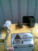
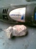
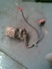
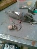
You might be able to do a gross dissection of what I take to be deceased CDI unit,that is to identify major organs,like the output pulse transformer,that's the thing that steps up the voltage coming out of the energy storage capacitor and connects to the plug cable, and the storage cap. itself ,probably a good sized round affair with a lead sticking out of it at each end.But you would have a hard time with the nervous system,wiring,IC's etc.
Frankly I'm kind of leery of the whole thing, not even sure it is a honest to goodness real life CDI!,it's probably not worth while shipping the corpse half way across the planet for my expert scrutiny.My aim is to come up with a HT charging system that people with your sort of background can put together with readily available parts and which of course works well.I have been to Aussiland,but only NSW & Queensland,skipped the Ayers rock, a real tourist magnet.Nice cities, impressive scenery,nice people and very good beer.My brother in law lives near Brisbane.
Frankly I'm kind of leery of the whole thing, not even sure it is a honest to goodness real life CDI!,it's probably not worth while shipping the corpse half way across the planet for my expert scrutiny.My aim is to come up with a HT charging system that people with your sort of background can put together with readily available parts and which of course works well.I have been to Aussiland,but only NSW & Queensland,skipped the Ayers rock, a real tourist magnet.Nice cities, impressive scenery,nice people and very good beer.My brother in law lives near Brisbane.
Last edited by a moderator: