Vintage look headlight, turn signals, tail, brake

Curious about your thoughts on this turn signal setup. It is particular to my bike because of the leaf spring struts. I have attached pics of the struts, front and rear to this post.

I have decided to use LED marker light replacement bulbs, front and rear (law says I need both). As RdKryton showed above, the LEDs will be separated from the base. I am then mounting the LED assembly in a plumbing end cap, probably copper (almost certainly). I will solder a thin brass plate to the end cap which will bolt onto the struts. More detail in the next post.
 

Attachments

  • turn signal detail_front.JPG
    turn signal detail_front.JPG
    75.5 KB · Views: 315
  • rear_light_detail.JPG
    rear_light_detail.JPG
    60.5 KB · Views: 319
The LEDs mounted in a copper end cap, with a brass plate soldered on (all painted gray to match) will bolt to the end of the strut with the acorn nut. By replacing the solid all-thread rod with a hollow lamp rod, I will be able to run the wiring inside the strut to the leaf, then route the wiring under the leaf to keep it out of sight.

I will use some variation of this technique. The question is whether I should mount it above or below the strut. I am leaning towards below. What do you think?

Thanks.
 

Attachments

  • preset_strut.JPG
    preset_strut.JPG
    7.5 KB · Views: 307
  • turn signals_1.JPG
    turn signals_1.JPG
    8.1 KB · Views: 287
  • turn signals_2.JPG
    turn signals_2.JPG
    8.4 KB · Views: 304
Last edited by a moderator:
I think below the strut is a good look. I am going to try to same kind of LED marker light but I may be able to use my original turn signal housings.

Jim
 
2 of the LED 1156 replcements do not trigger a thermal flasher either....however, I think I have an utterly simple solution. It will draw a bit more current than using 2 LED replacements alone, but will be much less than using 2 standard bulbs...and get me a cool little feature at the same time. Details to follow.
 
Had to work Saturday morning (took Weds. off to take my older son to the Chicago Auto Show)...but I made some progress in the afternoon.

A second look at the proposed law revealed the need for front turn signals in white or amber, so I got some 3157 replacement LED amber lights.

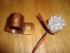
I will have some pics tomorrow, I hope, but here is what I did so far. A 3/4" copper pipe end cap is very, very close to fitting the LEDs. I wanted something as compact as I could because I thought that a compact tail light would look more in proportion and turn signals had to be smaller than the tail light for the right aesthetic. As RDKryton did, I removed the LED assembly from the bulb body. Even with the LEDs removed, they didn’t quite fit in the end cap (moving up to a 1 inch cap would have worked, but didn’t look right to me). I used my Dremel with a medium sanding drum to trim the edge of the circuit board around the LEDs down- that was what was too big. I also used the Dremel to grind out the inside of the end cap and got plenty of clearance- why this is important in a minute.

I found some copper coated pipe hangers that are used for copper pipe. It is a “U” shaped piece that has a 1/4” hole at the top of the “U” for hanging. I spilt the “U” at the bottom so that I am left with 2 “J” shaped pieces. This will provide a hanger for 2 lights. I then rounded of the corners of the “J”s and the “J” fits around the end cap and leaves a tab sticking out the top to bolt to the strut identified in a previous post. I attached the “J” tab to the cap by soldering...which is a nice advantage to using copper.

Back to the LEDs- I soldered a wire lead onto each lead. I then coated the back with silicone...because, after all, the case is copper. Now, back to the clearance issue around the edge of the circuit board. As you may know, there is a thin copper layer in there and if that touches the copper, the LEDs will not work due to a short. With some extra clearance, I can coat the edge of board with some non-conductive paint and put a skin of silicone inside the end cap and prevent the problem.

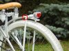
I really like the look- these things are very small and elegant...if I do say so myself....fit the look of the bike, and will get the job done.
 
OK- here are the pics of what I have so far. The first is a pic of the components, the end cap, the hanger and the LED.

The second pic is the assembled unit, with and without the LED. I put a skin of silicone inside the end cap and around the edge of the LED circuit board. This insulates the board from the end cap. It works well. Looks a lot easier than it was...but a simple look, not execution, is what I am after.

Next step is making the front turn signals, then paint.
 

Attachments

  • DSC00126.JPG
    DSC00126.JPG
    113.8 KB · Views: 295
  • DSC00127.JPG
    DSC00127.JPG
    127.3 KB · Views: 343
Very nice. Can't wait to see them installed and painted. LED's are cool to work with. Low current draw for our little batteries.
Jim
 
Glad to see the LED

I've been curious about the LED replacement 1156/1157. I want max hours as I can with my wee battery. Also love the execution of this to fit the look of the bike. Exactly the sort of thing I like to build in my shop as well (the hardwar store employees have stopped asking what I'm doing, they just ask, "another bike?" LOL!!!). Thank you so much for the excellent documentation in this project!!!
Question: I use an 1156 retro'ed into a cool housing for my Headlamp, How well would the LED 1156 work as a headlamp? Is the color rendering too sharp, and 'blue'? Again, I'm looking for as little draw on the system as possible for max use hours...
TIA
Rif
 
Back
Top