212 Golf Cart

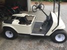
I know this has 4 wheels but the build is in the spirit of what we do here. A friend gave me a fairly nice Ezgo cart that needed too much
to repair the electrics. Having a new 212 and torque converter in boxes its a no brainer. About a zillion of these have been done, but as usual
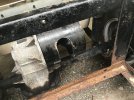
I opted for the hard way. Not wanting to build all the intricate structures most folks do I opted to use the case of the old motor. Required a lot of tedious, actually a little over an hour, cutting of the motor case. With the case opened I can run a drive shaft inside the case turning the original input shaft with Lovejoys being driven by a a chain from the Preddy. This keeps every thing in its original places drive wise. Much less complicated fab wise. And yes thats 1/2 steel I cut and hole sawed from the case. Speed calculations indicate a pretty good top end.

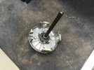
The brush holder now holds a flange bearing to support the shaft on the other end. Just waiting on Lovejoys now. Ignore the rusty parts, they will be handled.
 

Attachments

  • CDA53312-2F3A-4F9F-8DCF-41486B2250FC.jpeg
    CDA53312-2F3A-4F9F-8DCF-41486B2250FC.jpeg
    246.9 KB · Views: 3,288
  • 0419F322-77A7-4E3C-8F6B-9B51076A257D.jpeg
    0419F322-77A7-4E3C-8F6B-9B51076A257D.jpeg
    256.2 KB · Views: 172
  • 814352DD-163F-42C9-9955-EF763E9BA54C.jpeg
    814352DD-163F-42C9-9955-EF763E9BA54C.jpeg
    260.5 KB · Views: 166
  • 74B54E0D-0D4E-4E8F-B502-5E5A4FF888C9.jpeg
    74B54E0D-0D4E-4E8F-B502-5E5A4FF888C9.jpeg
    381.4 KB · Views: 170
  • FA168D7D-2D74-4B33-9BA6-AA3E80813E66.jpeg
    FA168D7D-2D74-4B33-9BA6-AA3E80813E66.jpeg
    363.6 KB · Views: 175
The unit is a slip fit thru out. The original unit(Comet) is straight 5/8, circlipped on the end and drawn tight with the nut
on the driver. The way I run them is with lock collars on both ends so I can use various length shafts. The only down side to this is the stock driven sprocket is not locked to the key/shaft and floats a bit. After years of doing it this way
I have found wear not an issue. To run a pulley on the driven you will have to cut it down to the pulley only, no set screw. You cant space the driven much farther than that or you run out of crankshaft for the driver, The backing plate is thicker these days as its cast not steel like the old ones. This aggravates the problem of spacing in the driven. Hope this explains what you are asking.
 
I will add here there are pulleys that have the set screw in the middle of the sheeve maybe an A type? These would require no mods to work.
 
The unit is a slip fit thru out. The original unit(Comet) is straight 5/8, circlipped on the end and drawn tight with the nut
on the driver. The way I run them is with lock collars on both ends so I can use various length shafts. The only down side to this is the stock driven sprocket is not locked to the key/shaft and floats a bit. After years of doing it this way
I have found wear not an issue. To run a pulley on the driven you will have to cut it down to the pulley only, no set screw. You cant space the driven much farther than that or you run out of crankshaft for the driver, The backing plate is thicker these days as its cast not steel like the old ones. This aggravates the problem of spacing in the driven. Hope this explains what you are asking.
Thanks Sir! That's the info I was looking for. Just for you reference. The Bravex brand torque convertor uses the heavy cast aluminum backing plate, the torque convertor is also made in Plainfield Illinois, they are a 1½times more money than other torque converters, but twice as nice as the knock offs. Thanks again for info & sorry for all the questions, lmao but you saved me a bunch of money, from not buying something I dont need. If you get tired of me just tell me to get F'd & I'll leave 🤣😂🤣
 
Thanks Sir! That's the info I was looking for. Just for you reference. The Bravex brand torque convertor uses the heavy cast aluminum backing plate, the torque convertor is also made in Plainfield Illinois, they are a 1½times more money than other torque converters, but twice as nice as the knock offs. Thanks again for info & sorry for all the questions, lmao but you saved me a bunch of money, from not buying something I dont need. If you get tired of me just tell me to get F'd & I'll leave 🤣😂🤣
I am always glad to help anyway I can, I dont mind questions.
 
Heres a few pics of the converter setup. This applies to bikes as well. With the driver spaced to be even with the driven
or very close there is precious little crankshaft left(slightly less than 1/2”) to run the outer driver. I have run these out of alignment to see the effect but nothing much happened detrimentally. I would prefer them aligned but think more crank is better than perfect alignment. Will remove 1 shim, I made a stack of 1/4” washers along with a gr8 bolt to apply heavy clamping to the crank. The problem comes from changing the mounting plate from steel to cast, that pushes the whole thing farther out on the crank.

Got the mounting plate. This is a good one thick and stiff compared to some. Beware of the thin ones. Also got the dynamo. Its a tad bigger than I thought but will mount easily. Its very simple, basically a motorcycle generator in a case.
 

Attachments

  • 3A9C1A1E-6561-45A7-9BD5-CAE2DA097771.jpeg
    3A9C1A1E-6561-45A7-9BD5-CAE2DA097771.jpeg
    152.7 KB · Views: 80
  • A4253924-82B5-4B36-8CD4-BFDE9D36C49B.jpeg
    A4253924-82B5-4B36-8CD4-BFDE9D36C49B.jpeg
    142.9 KB · Views: 75
  • 47A3B9AB-E65C-4931-BD61-1360D6A71AED.jpeg
    47A3B9AB-E65C-4931-BD61-1360D6A71AED.jpeg
    127 KB · Views: 81
  • 1BC61E09-53CE-4715-8AE2-34B8415168B3.jpeg
    1BC61E09-53CE-4715-8AE2-34B8415168B3.jpeg
    171.3 KB · Views: 83
  • B8C120DA-8E82-46FE-9BC5-2D8FE9CB5F91.jpeg
    B8C120DA-8E82-46FE-9BC5-2D8FE9CB5F91.jpeg
    164.7 KB · Views: 102
Heres a few pics of the converter setup. This applies to bikes as well. With the driver spaced to be even with the driven
or very close there is precious little crankshaft left(slightly less than 1/2”) to run the outer driver. I have run these out of alignment to see the effect but nothing much happened detrimentally. I would prefer them aligned but think more crank is better than perfect alignment. Will remove 1 shim, I made a stack of 1/4” washers along with a gr8 bolt to apply heavy clamping to the crank. The problem comes from changing the mounting plate from steel to cast, that pushes the whole thing farther out on the crank.

Got the mounting plate. This is a good one thick and stiff compared to some. Beware of the thin ones. Also got the dynamo. Its a tad bigger than I thought but will mount easily. Its very simple, basically a motorcycle generator in a case.
Cannonball3 what kinda measurement do you got on your drive & driven pulleys from the back plate to the back edge of your pulleys? I know you mentioned this is the farthest you would space pulleys out. Thanks again!!!
 
Will have to measure later as the converter is disassembled now. I had to add a shim on either side of the stock driven sprocket to clear the #40 chain that only made matters worse. Running inboard like you have it, would only require the very minimum of shimming just to clear the mounting plate on the converter side.
 
Heres a few pics of the converter setup. This applies to bikes as well. With the driver spaced to be even with the driven
or very close there is precious little crankshaft left(slightly less than 1/2”) to run the outer driver. I have run these out of alignment to see the effect but nothing much happened detrimentally. I would prefer them aligned but think more crank is better than perfect alignment. Will remove 1 shim, I made a stack of 1/4” washers along with a gr8 bolt to apply heavy clamping to the crank. The problem comes from changing the mounting plate from steel to cast, that pushes the whole thing farther out on the crank.

Got the mounting plate. This is a good one thick and stiff compared to some. Beware of the thin ones. Also got the dynamo. Its a tad bigger than I thought but will mount easily. Its very simple, basically a motorcycle generator in a case.
Cannonball3 what kinda measurement do you got on your drive & driven pulleys from the back plate to the back edge of your pulleys? I know you mentioned this is the farthest you would space pulleys out. Thanks again!!!
By looking at your pic, it appears you got about 1" between backing plate & backside of driver pulley. I'm no big hurry on that measurement, just curious. Your engine mounting plate, is it a OMB warehouse brand 1?
 
By looking at your pic, it appears you got about 1" between backing plate & backside of driver pulley. I'm no big hurry on that measurement, just curious. Your engine mounting plate, is it a OMB warehouse brand 1?
It came from jr-metal-creations on ebay. Nicely done, clean precise slots, I believe it was water sawed. Im removing one shim on the driver will measure when I reassemble. If all goes well may ride this pm.
 
By looking at your pic, it appears you got about 1" between backing plate & backside of driver pulley. I'm no big hurry on that measurement, just curious. Your engine mounting plate, is it a OMB warehouse brand 1?
Will have to measure later as the converter is disassembled now. I had to add a shim on either side of the stock driven sprocket to clear the #40 chain that only made matters worse. Running inboard like you have it, would only require the very minimum of shimming just to clear the mounting plate on the converter side.
I cant remember, but what was your reason to need to space your torque convertor pulleys out farther? Was it due chain width? Or other reasons? Thanks.
 
Back
Top