Dserna
Member
- Local time
- 8:23 AM
- Joined
- Mar 21, 2020
- Messages
- 57
Is there any other tips to get more compression? My motor is only a 49ccA glass top coffee table works just as well as a mirror, that's just what i had that was perfectly flat.

Is there any other tips to get more compression? My motor is only a 49ccA glass top coffee table works just as well as a mirror, that's just what i had that was perfectly flat.
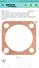
How about this gasket.Is there any other tips to get more compression? My motor is only a 49cc
Generally they have to be at a level higher than the carburetor, I just so you know boost bottles are just a selling gimmick I will not give you extra power at allDoes the boost bottle have to be mounted in a certain position? Or can I mount it where I show in the picture?
Yes, or sand the cylinder head or use a thinner basegasket or headgasket.One way to reduce squish is to deck the cylinder by sanding the top of the cylinder down some.
Do you have information on compression and port timing? Someone told me to use more gaskets on the base to alter the timeing instead of taking the chance of cutting it. I already cleaned up the crank case and widened my ports a little but i need help, and you know what you're talkingYes, or sand the cylinder head or use a thinner basegasket or headgasket.
FIRST you have to know what the squish is so you can set it at optimum.
The easiest way to measure it is with a piece of solder down the sparkplug hole.
View attachment 94064
Solder should be over the pin so piston rocking does not affect it. Turn the flywheel over by hand.
Use 1mm to 1.5mm (0.040"-0.060" lead or electrical or rosin core solder.
Here is a video of another way (Jeff Slavens): How-to Measure Squish Clearance Part 1
Then measure how much it has squished at the very outer end near the cylinder wall:
View attachment 94065
A big problem is that the squish area on the head does well match the piston:
View attachment 94066
On the left is the ideal squish area. The right side does not match the dome of the piston and the bowl is not large enough.
Many of our motorized bikes have these problems and some don't even have a squish area:
View attachment 94068
No squish area or too far from the piston or not matching the piston's dome leads to this problem:
View attachment 94067
The mixture is not kept in motion, it has rich and lean spots, it burns slowly and often detonates at the far end.
So how can we get the head to have a squish area that matches the piston dome?
Easy if you have a lathe, without one you have to be resourceful. Using coarse sandpaper you can use a piston (preferably old one) to grind and lap a quench area into a head, which is exactly what I did with the head on the upper left (above cylinder heads photo), or make up your own tool like this:
View attachment 94069
Even a mild steel cutter, 3 or 4 mild steel cutter bars welded to a bolt shank, will do the job.
Clamp the head tight in the drill press!
Maestro at work:
View attachment 94070
Once you have the squish area cut, sanded or ground, you need to sand or lap the gasket surface.
Lay out a piece of sandpaper on a flat surface like a sheet of glass.
View attachment 94071
Start with coarse grit to remove a lot of metal and then use medium for better finish.
I mentioned that you can also use a thinner headgasket to get your measurement if needed.
If both head and cylinder are sanded perfectly flat teflon tape (plumber's tape) can be used to seal the head.
This is the stuff:
View attachment 94072
Twist it into a continuous ring on the top of the cylinder, hold it in place with a daub of grease and torque the head down.
Easy Peasy. Compression squeezy. Moreover it seems to transfer heat well. Do NOT do this if you don't know your squish.
Piston too close to head will cause major damage. Remember that rods and clearances stretch at 8000 rpm.
Good luck!
Yes, or sand the cylinder head or use a thinner basegasket or headgasket.
FIRST you have to know what the squish is so you can set it at optimum.
The easiest way to measure it is with a piece of solder down the sparkplug hole.
View attachment 94064
Solder should be over the pin so piston rocking does not affect it. Turn the flywheel over by hand.
Use 1mm to 1.5mm (0.040"-0.060" lead or electrical or rosin core solder.
Here is a video of another way (Jeff Slavens): How-to Measure Squish Clearance Part 1
Then measure how much it has squished at the very outer end near the cylinder wall:
View attachment 94065
A big problem is that the squish area on the head does well match the piston:
View attachment 94066
On the left is the ideal squish area. The right side does not match the dome of the piston and the bowl is not large enough.
Many of our motorized bikes have these problems and some don't even have a squish area:
View attachment 94068
No squish area or too far from the piston or not matching the piston's dome leads to this problem:
View attachment 94067
The mixture is not kept in motion, it has rich and lean spots, it burns slowly and often detonates at the far end.
So how can we get the head to have a squish area that matches the piston dome?
Easy if you have a lathe, without one you have to be resourceful. Using coarse sandpaper you can use a piston (preferably old one) to grind and lap a quench area into a head, which is exactly what I did with the head on the upper left (above cylinder heads photo), or make up your own tool like this:
View attachment 94069
Even a mild steel cutter, 3 or 4 mild steel cutter bars welded to a bolt shank, will do the job.
Clamp the head tight in the drill press!
Maestro at work:
View attachment 94070
Once you have the squish area cut, sanded or ground, you need to sand or lap the gasket surface.
Lay out a piece of sandpaper on a flat surface like a sheet of glass.
View attachment 94071
Start with coarse grit to remove a lot of metal and then use medium for better finish.
I mentioned that you can also use a thinner headgasket to get your measurement if needed.
If both head and cylinder are sanded perfectly flat teflon tape (plumber's tape) can be used to seal the head.
This is the stuff:
View attachment 94072
Twist it into a continuous ring on the top of the cylinder, hold it in place with a daub of grease and torque the head down.
Easy Peasy. Compression squeezy. Moreover it seems to transfer heat well. Do NOT do this if you don't know your squish.
Piston too close to head will cause major damage. Remember that rods and clearances stretch at 8000 rpm.
Good luck!
I have no squish.. I taped the peace of solder to the piston and tried it and the soder was untouched. However I did put more base gaskets in to adjust the timing. But not as much as the width of the solder, so theres no way I even had a good squish gap before that. I'm using a copper head gasket at .5mm. The piston is .85mm from the edge of the top of cylinder. I know I need to adjust the cylinder but should I adjust the head as well?? And the piston should be level with the cylinder top right?