Easily Removable Staton Friction Drive Build Idea

nmbiking

New Member
Local time
6:46 PM
Joined
Aug 22, 2022
Messages
10
Hi,

I've read through a lot of the posts on this forum and gathered a lot of great information/advice along the way.

Ideally I'd have a dedicated motorized bike, but funds and space make that impossible at the moment.

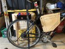
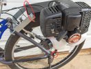
So, I've decided to make a homespun frame mounted setup I'm about halfway through with. The idea is it'd be removable/replacable in about 15 minutes with about 8 bolts/nuts total. I'm planning on putting an inline trailer light plug splice in the kill switch wiring, and zip tieing the throttle to the handlebars each time. I bought a 1 1/8" roller kit with a Zenoah two stroke.

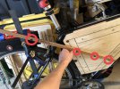
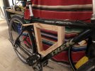
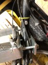
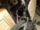
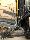
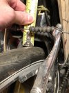
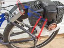
My bike's seat stay doesn't give enough room to comfortably use the Staton supplied U-bracket, so I built this goofy box for the seemingly strong triangle core of the frame (outlined in sharpie in the picture). Not pictured are two pieces of 1 1/4" angle iron I'm going to through-bolt to the plywood frame on opposite sides. Planning on grinding that down to ~ 3/4" wide in the peddling area for a combined width (including the plywood box) of 4", That angle iron is mocked up by the small stick in my picture, with the red circled spots eventually being 5/16" through bolts with nylon lock nuts, and using the supplied 3/8" bolt for the aluminum drive kit. I'm planning on padding the rear of that mounting assembly out with 3/4"x1 1/2" steel square stock to match the required width of the Staton drive kit (~4"), and using some 3/16"x1 1/4" flat bar to jury-rigged to the final connection.

Long story short, I'm wondering if anyone on here has gone this route/can warn me of potential pitfalls. I'll try and post a few pictures of progress, which has been kinda slow thus far.

Thanks!!
 

Attachments

  • IMG-0987.jpg
    IMG-0987.jpg
    245.1 KB · Views: 190
  • IMG-0988.jpg
    IMG-0988.jpg
    221.8 KB · Views: 214
  • IMG-0701.jpg
    IMG-0701.jpg
    193.5 KB · Views: 202
You have a strange frame there. Can't see exactly what's going on just above the rear Vbrake. Seems you have 2 rear frame stays going into 1 tube then into the seat frame tube. Is there a hole for a reflector/caliper brake in the frame just above the rear Vbrake? Any close-up pics of that area would help a lot with your tools removed.
 
Dude....that really looks like overkill. 🤯

Staton is the way to go....have you actually tried the U-bracket on the frame yet?
I'd figure a way to make it fit.

The Staton kit is very easy to install, it's light weight, and extremely durable.
The engine can be removed very easily, leaving just the u bracket, friction channel with roller/clutch bell, and the 2 support rods.
When the engine is unmounted, it kind of looks like a regular bike rack...which would probably be doable for your situation.

The engine is attached to the kit with only 4 bolts, and easily removed in less than 5 minutes.👍
Then, unhook the throttle cable from the engine....again, super easy.
Lastly, you'd just use a bullet quick connector to attach & detach the kill switch.
Done.
 
Thanks for both of your replies. Here are a few pictures without the stuff in the way. It is exactly that, two tubes feeding into one. Only 1/2” clearance between the wheel and the bottom of that tube, which has a small hole in it, I figured probably a condensation weep hole.

I thought about grinding part of the U bracket down for a bit more clearance, but that still seems super close to the wheel.

It is certainly going to be overbuilt. I like the idea of taking the motor off, but worry about eventually wearing the treaded mount holes in the engine out.
 

Attachments

  • E7A1E2C7-97EB-4FA0-BCB9-1077C4C32B8F.jpeg
    E7A1E2C7-97EB-4FA0-BCB9-1077C4C32B8F.jpeg
    172.9 KB · Views: 179
  • 49D4C04D-EEA9-4F6A-BAAD-88A090396244.jpeg
    49D4C04D-EEA9-4F6A-BAAD-88A090396244.jpeg
    195.2 KB · Views: 172
  • 12353356-EFAF-4089-8583-E77EA5A00BF1.jpeg
    12353356-EFAF-4089-8583-E77EA5A00BF1.jpeg
    201.3 KB · Views: 155
  • 3F32EB13-D3DB-441C-8E87-630CB2F1EF89.jpeg
    3F32EB13-D3DB-441C-8E87-630CB2F1EF89.jpeg
    171.8 KB · Views: 156
Looks like you could drill a hole in the tube right above the V brake for the U bracket's center bolt to go through. Here's how I kept my rear disc brake. Be creative but keep it simple

20210216_221805.jpg


20210215_160252.jpg

20210519_154823.jpg

IMG_20221001_121413.jpg
 
Notice the reinforcing mods I did to the bracket. The bracket parts will fit into the sides of thick unistrut. This will allow you to really tighten the bracket down without bending it. I also welded thick unistrut to the side of the bracket for a tensioner sprocket guard.

20210215_160252~2.jpg
 
Drill a hole...or do what ever you have to do to make that U-bracket work.
After it's installed, and tightened down good, life will be easy.

If you are worried about the engine threads eventually getting stripped(rightfully so), there's another option without removing the engine from the FD kit. Just remove the entire FD kit w/engine attached......1 long bolt connecting the u-bracket to the black FD channel, and one 5mm screw from the bottom of each support rod on the lower frame. Then you'll just unplug the bullet for kill switch and disconnect the throttle cable.
You'll only be left with the "permanent" U-bracket.

Want to make it even easier?
Just remove the long bolt from the black FD channel, but leave the support rods on, angle them forward toward the u-bracket, and then just zip tie them to the u-bracket.
 

Attachments

  • Screenshot_20221009-010828_Samsung Internet.jpg
    Screenshot_20221009-010828_Samsung Internet.jpg
    161.9 KB · Views: 140
  • Screenshot_20221009-010828_Samsung Internet.jpg
    Screenshot_20221009-010828_Samsung Internet.jpg
    166.4 KB · Views: 152
Woah, those are some great ideas! Thanks!

It’s technically my dad’s bike so I’m reluctant to drill any holes in the aluminum frame. That unistrut is a heck of a good idea, though. As is zip-tieing the support rods to the bike when not in use. I’m happy I shelled out the extra few bucks for the Staton kit. It took them over a month to send it but I like thinking it was made in a small Oklahoma shop.

I’ll post a few pictures when I get the whole thing put together.
 
What's weird about his rear stays is that they're almost 90deg in relation to the wheel. I wonder if 4.2in extensions might work? I've used them before and the unit is still solid if they're kept tight.
3322.jpg
 
Happy New Year! I finished my project today (save final paint and a few details). Took it out for a couple of rides today.

Seems to be pretty solid. I might try adding some rubber plumbing gasket material between the frame and unit to reduce vibration a bit.
 

Attachments

  • IMG-1484.jpg
    IMG-1484.jpg
    226.3 KB · Views: 114
  • IMG-1482.jpg
    IMG-1482.jpg
    447.4 KB · Views: 118
  • IMG-1481.jpg
    IMG-1481.jpg
    347.4 KB · Views: 151
Back
Top