I was wondering if anyone has mounted a key switch to their bike i was also thinking of mounting it into a small plastic/metal box. I would also like to have a green led for when the switch is engaged.
I just drew up a quick circuit that should work. The only problem is, I'm unsure of the exact output voltage of the blue wire, so the resistor value will need to be trial and error.
I've heard that the voltage may be as high as 120V, so for R1 I'd start with a 6K8, 5W (ceramic) resistor, then work down in resistor value until the LED brightness is about normal. Stick to 5W resistors, though, or they'll get too hot.
eg 6K8, 5K6, 4K7, 3K3, 2K2 etc. They cost 20 or 30c each at any electronics hobbyist store, so buy 5 or 6.
If the LED looks
really bright, stop the engine and change to an even higher higher resistor value.
If the resistor value is
way too low, the LED may fail or the engine might not start. That's why it pays to work down in steps.
Don't worry if the resistor gets a bit hot - that's normal
Typical average LED current is supposed to be about 20mA, if you have a multimeter. An analogue meter or 'True RMS' DMM would be best for this. Otherwise, just go by brightness, but don't try to light a normal green or red LED 'super-bright' - it
will fail.
N.B. It could be done better using the white wire, but then you'd need an ignition switch with
normally closed contacts, that open when the ignition is 'on' - probably hard to find.
Let us know how you go.
... Steve
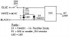
The circuit:-
(The resistor, R1, limits current through the LED to a safe level and the 1N4001 diode, D1, prevents the high reverse voltage from damaging the LED when the polarity of the blue wire goes positive.)
- Just noticed, in 'Parts' below, I said start with a 5K6 resistor, but a 6K8 as mentioned above is even better for the first test... S