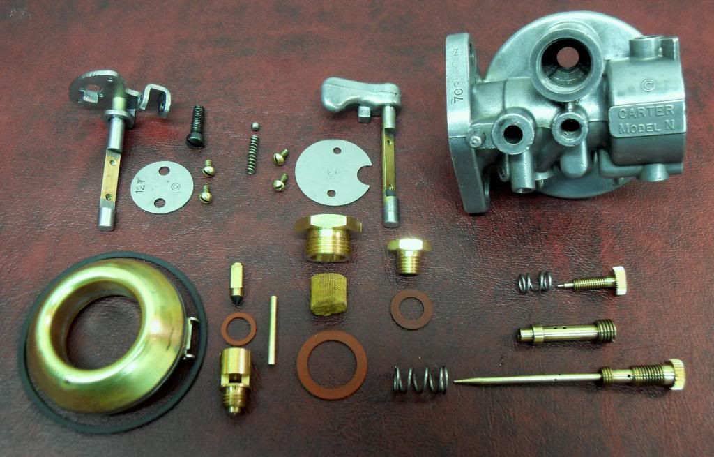
Moving on to assembly of the 703S…
A good place to start is the throttle shaft assembly. Start by inserting the shaft into the top of the carburetor body, with the center flat area facing toward the mounting flange (toward engine.) The throttle plate is a close fit, so it can be a bit of a headache getting it aligned on the shaft. Since the edges of the plate are beveled to fit the throttle bore, it's important that the plate be properly positioned end-for-end. The stamped trademark "C" on the plate should be towards the idle port side of the throttle bore (arrow points to idle port):
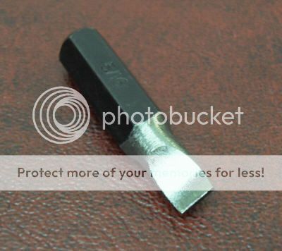
Another ticklish operation is getting the throttle plate screws started. Some kind of screw-starting tool is almost a must. I used one of those screwdrivers with a split blade. The two halves of the blade are expanded apart by moving a collar on the screwdriver shaft, thus lightly gripping against the inside of the screw slot:
The screw-starting tool is only used for getting the screws started -- a regular screwdriver should be used for final tightening. There is a process for tightening the screws: first, just run the screws down to where the heads are barely contacting the throttle plate. Then, gradually advance the screws while simultaneously rocking the throttle shaft lever back in forth. This allows the plate to align itself within the throttle bore. With the screws tightened, check for free movement of the throttle shaft, and complete closing of the plate. Also, it's a good idea to use Loc-Tite on these screws, and be careful not to to over-torque them.
The choke valve can also be a bit of a pain to install, but mainly because of the spring-and-ball detent mechanism. Start by coating the spring and ball with multi-purpose grease (I used "Superlube" synthetic grease.) This is not only for lubrication, but also to help "glue" these parts in place during the first phase of assembly. With the carburetor resting on the bench with inlet end facing up, insert the spring into the correct hole (opposite the lever side), and carefully place the 1/8" diameter detent ball on top of the spring. Looking through the choke shaft hole, you should see something like this:

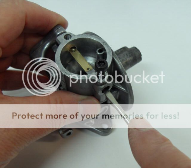
Next, temporarily thread some kind of 8-32 screw into the hole just above the detent ball. It only needs to go in a few threads -- not so far that it enters the cross hole for the choke shaft. (It's only purpose is to prevent the ball from hurtling skyward, should the installation process go horribly wrong.) Next, insert the choke shaft into the carburetor body, from the end opposite the spring and ball, just to the point where the end of the shaft contacts the spring and ball. With the choke shaft held in this position, use a small flat-blade screwdriver to compress the top of the ball against the spring, whilst simultaneously applying light pressure to the lever-end of the choke shaft. The idea here is to compress the ball and spring to the point where the choke shaft can pass over the top of the ball. Here's what the process looks like:
With the choke shaft in place, the choke plate can be installed in a manner similar to the throttle plate. The choke plate is easier, since it is closer to the open end of the carb. Note the semi-circular notch in the plate which goes toward the bottom. I installed mine with the trademark "C" toward the outside, but it really doesn't matter in this case.
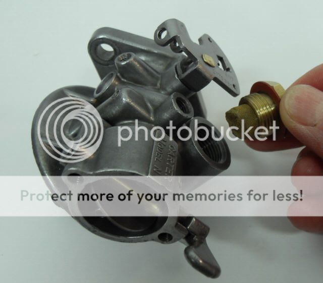
The fuel strainer, strainer nut, and gasket can be installed next. The brass fuel strainer should be a close fit in the strainer nut. It is held in place by three ribs in the bottom of the inlet well, once the fuel strainer nut is tightened.
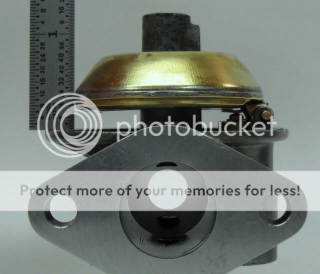
With the new inlet valve needle, seat, and gasket installed, the float level can be set. With the carburetor inverted, and the float resting lightly against the needle, the "lower" edge of the float should be 13/64" from the machined surface of the bowl flange. This should result in the float being almost exactly parallel with the bowl flange:
If it's not, remove the float and bend the small tab which contacts the needle. Only very slight movement of this tab is required to make a significant difference in float height.
The remainder of the assembly is pretty straightforward. Temporarily remove the float, so it doesn't get wrenched out of alignment, until just before installing the bowl. The nozzle (12-329) can now be installed in the lower end of the body. Avoid excessive tightening. The high speed adjusting needle (11-192S) and spring can now be installed from the top side. Hand-tighten the needle until it just seats against the nozzle, then back it off 2 full turns, for a preliminary adjustment.
Likewise, the idle adjustment screw (30A-46) and spring can be installed. Hand-tighten the screw until it just seats, then back it off from 1 to 3 turns, for a preliminary adjustment. Install the throttle stop screw in the throttle lever. Adjust it so that the throttle valve is held open about 1/32", or so.
Install the new bowl gasket. Since this gasket expands somewhat from fuel contact, it will have a considerably smaller free diameter than the corresponding slot in the bowl flange. It takes a bit of deft finger manipulation to work the gasket down into its slot, but it's not all that difficult. All that remains is to re-install the float, and install the bowl. Be sure to visually center the bowl on the bowl gasket before tightening the bowl nut. Also, don't forget the bowl nut gasket.
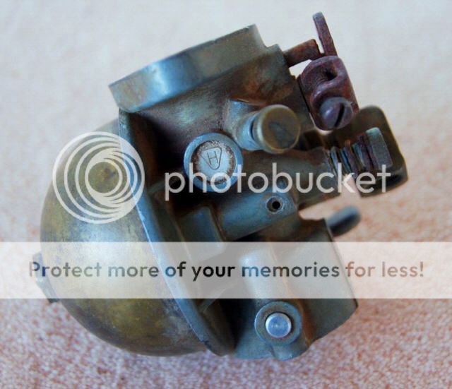
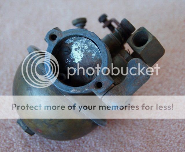
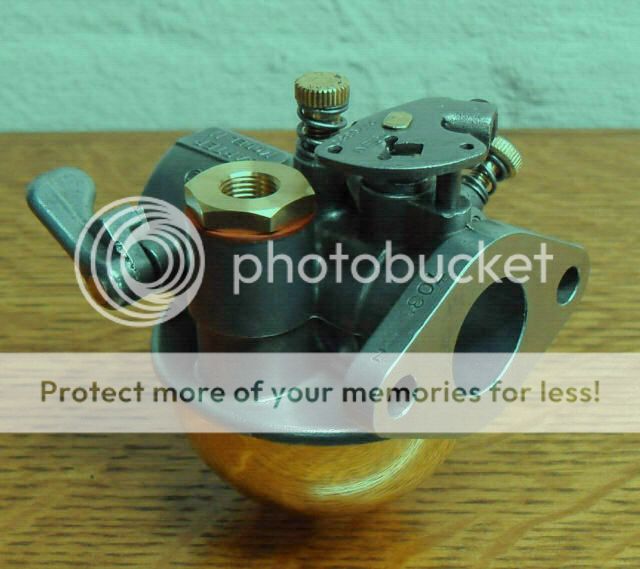
Here are a couple of views of the assembled 703S carburetor:
For final adjustment of this model carburetor, the following instructions are copied from the Carter/Whizzer instruction sheet:
"After rebuilding and installation on engine is complete, the high speed and idle screw adjustments must be made.
The high speed needle should be adjusted for the leanest possible mixture which will allow satisfactory acceleration. With the high speed needle turned counter-clockwise (from closed position) 2 full turns, and idle screw turned 1 to 3 turns open, start engine.
Accelerate engine and check response. If the engine misses and backfires, the high speed mixture is too lean and the adjustment screw must be turned counter-clockwise to correct this condition. If the engine loads (heavy exhaust) and is sluggish, the mixture is too rich and the adjustment screw must be turned clockwise to correct.
To make the final check of the high speed adjustment, operate the engine under load and adjust. The idle screw should be adjusted intermittently while making the high speed adjustment. The final idle adjustment should be made at approximately 1000-1200 RPM until smoothest possible idle is obtained. This adjustment must not exceed the limits of 1 to 3 turns from closed position.
DO NOT USE EXCESSIVE FORCE ON THE HIGH SPEED NEEDLE OR IDLE SCREW AS DAMAGE MAY RESULT."
Paula