Whizzer Wiring Diagram

KilroyCD

Active Member
Local time
4:30 AM
Joined
Dec 3, 2007
Messages
1,376
Location
Lancaster County, PA
I've been asked to e-mail the Whizzer wiring diagram quite a few times, so I thought I'd just put it on the site. For some reason, I couldn't post the pdf file of this even though it's well within size limits, so I rescanned it as a jpg file and resized it so it should print out at actual size. It just isn't as high quality as the pdf file.
This is for the WC-1 and NE-5 models. I'm not sure if the NE-R uses the same wiring harness. This diagram will not apply to the Ambassador.
 

Attachments

  • WhizzerWiringResized.jpg
    WhizzerWiringResized.jpg
    61.1 KB · Views: 10,493
Just a side Bar from Helmutt

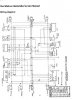
During the process Of designing a fine Kit Bike Frame system Powered By the whizzer Motor. there was the Ugly detail of the wiring and the Modules. Hanging all over out in space???


This detail was addressed with the dual rail frame design.. and being perfected with the New Helmutt Frame system. Made On purpose to be Hiding the Ugly modules Inside what looks to be a tool Box.and Using the right side frame rail for Conduit wiring inside the frame

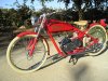
The CID,ACDC relay,voltage regulator Modules,Ket Switch,fuse,and the Battery all House Inside this simple fix, "the tool box" with a hiden vent for the wire to inter and travel out of.... then with a Mutistrand 9 wire. diving out through the vent,into the right side frame rail, used as conduit going forward to tie the forward Handle bar Control leads/ The wire connects are then Junctioned In the Back Cavity of the Head Lamp, as is done on many Motorcycles.... this simple Idea did cleanup,and protect all of this vulnerable vital articals,and still allows all of the electrical Functions that came On the Modern replica whizzers.. Running lights, dual beam head lamp,Brake lights, horn, lighted gages with Tac functioning.. as Is shown here with Joe Persons Fine Build We sent Joes Helmutt Bike frame Kit system with Color, and Modified whizzer center stand, and prewired.. ready for Joes Lovly final assembly. Feel free To call,and ask if ya Have any questions about this detail/or the general electrical of the stock Whizzer Motorbike 602-405-0394..
Kramer @ Helmutt Cycles
 

Attachments

  • !cid_A219FDB0129346D383DC010CA05542C8@JoeandJoycePC.jpg
    !cid_A219FDB0129346D383DC010CA05542C8@JoeandJoycePC.jpg
    213.6 KB · Views: 20,224
Last edited:
The pdf file finally...

With the recent change here to a new server I thought I'd try to upload the wiring diagram in the pdf file one more time. My previous attempts were unsuccessful despite the file being well within limits. Lo and behold I was successful this time, so here it is.
 

Attachments

  • WhizzerWiring.pdf
    5.5 MB · Views: 2,179
I just wanted to Thank You Quenton for all your help with my wiring harness. Without your help I could have never got that bike running. Your knowledge of all things Whizzer is truly amazing. Going out of your way to help me even in the midst of the Portland show and other things in your busy schedule is greatly appreciated! You are truly a great ambassador for Whizzer motor sports enthusiasts!
For anyone new here, who does not know who Quenton is, he is the leading authority on whizzer motorbikes and will go out of his way to help anybody who asks him. I just wish I had known him before I had started my project because he could have saved me hundreds of dollars more than he did!
Quenton, that new H-motor will be will be coming to you for that rebuild as soon as I can find a Tillotson ML5B Carb. I can't seem to find one anywhere. Anyone who has one please contact me @ lillback44@yahoo.com.
Thanks Quenton for all your help,
Chris in Ft Wayne
Ps: sorry I took so long!
 
Isn't that the same lilback that had a hussy fit and said he was done with the forum and its people? I'm guessing my suggestion didn't work either?
Bike came out so nice after quenton tackled it, that you pieced it out on eBay huh?
Only option I see for you is try to buy the knowledge.....wait!.....you are
 
Ambassador wiring

Any help in getting a diagram for an Ambassador? how much difference is the diagram in this thread? I'm helping a friend with his bike. no spark at the plug.
 
NE Ignition Wiring_Model.jpgBest if you contact me if the following information doesn't help, as there are several parts that are different from the standard harness.
The CDI and the tachometer are very different as they appear to be digital [Ambassador and NE-r Tachometer won't work on earlier models].

Make sure the green wire on the CDI ISN"T at ground when trying to start. Also check to make sure one side of the coil is grounded. If the rear wiring harness is un-pluged it removes a hidden ground and won't fire.


I have found several issues in the wiring at the CDI plug as the wires are reversed. I will attach the basic ignition wiring diagram for the later motors. Please note pins #5 & #6 on the CDI as this is where the wires were reversed on several Ambassadors.

If this doesn't help, please contact me directly and I will help you restore fire to your motor.

Have fun,
 
Back
Top